.png?imageMogr2/format/webp)
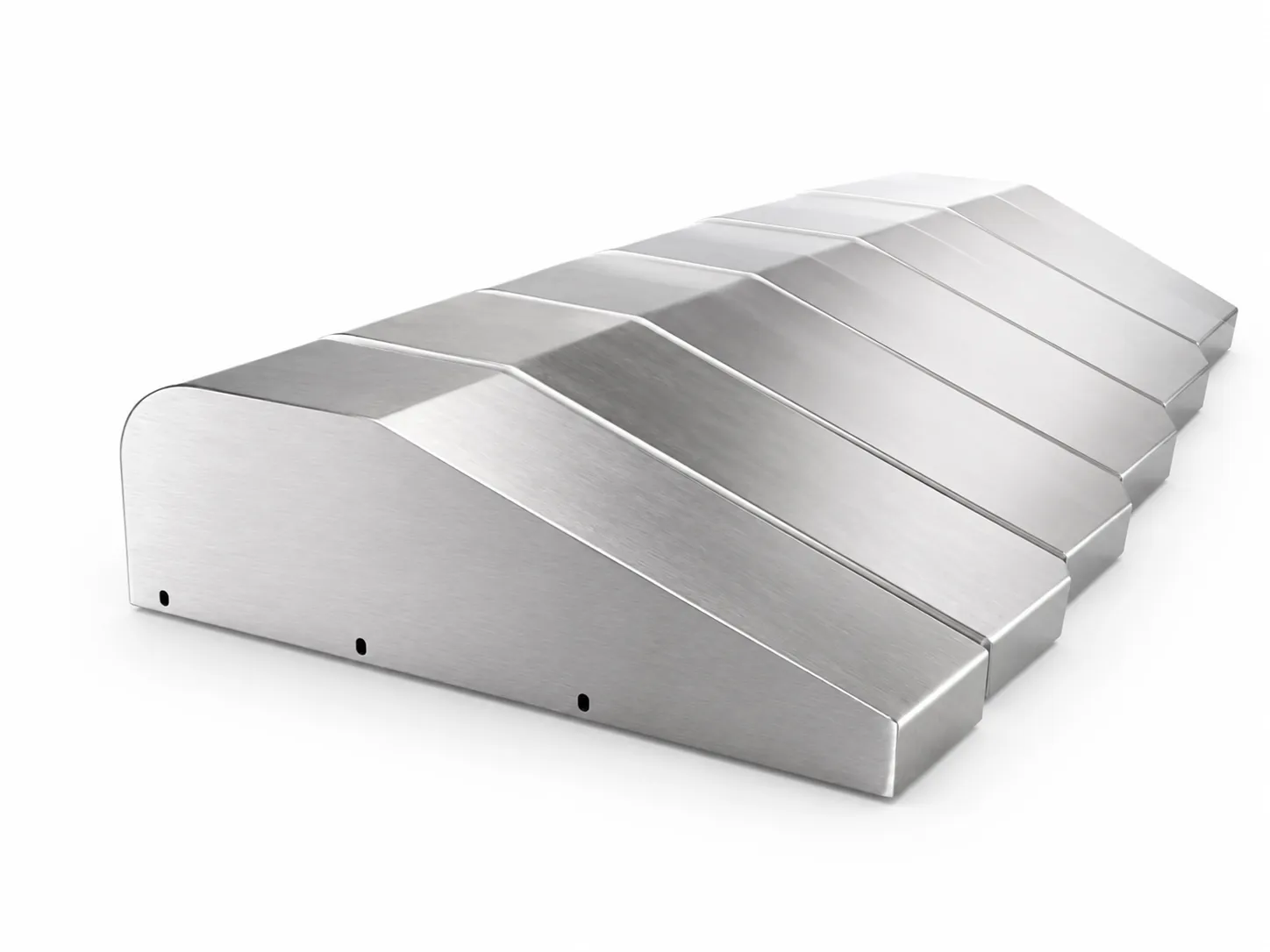
A sheet metal enclosure is sized from the panel that goes inside it, not from the outside. See what fixes the dimensions, the IP rating and the cutouts.
An electrical enclosure is usually the last thing drawn and the first thing to cause trouble. The reason is that its dimensions are not invented on the outside; they are the sum of what has to fit inside it — the components, the clearance around them, the radius a cable needs to turn, and the space a hand needs to reach a terminal. Designing the box before the layout is settled is the single most common cause of a second revision on a panel project.
The Enclosure Is Sized From the Inside Out
A sheet metal enclosure for a control panel is defined by its internal cavity, and the cavity is defined by four measurements that come from the electrical design rather than from the sheet metal drawing: the footprint of the components, the clearance needed above and below them for heat and wiring, the depth required by the deepest item plus its wire bend, and the working space a technician needs to land a conductor or swap a device.
The external size then follows mechanically: cavity plus sheet thickness plus the return on each edge plus, if the door sits proud, the door thickness and the compressed height of the gasket. Fabricators see the failure mode constantly — a customer fixes a 600 by 400 footprint early because it suits the wall it hangs on, then discovers during assembly that the DIN rail stack needs a depth the box does not have. Cutting the box deeper afterwards means new blanks, new folds, and a new coating batch.
The Mounting Plate Is the Real Interface
Inside every panel there is a second part that carries the actual engineering: the mounting plate. It is where the holes are, and those holes are what the electrical designer has to get exactly right, because a plate with a regular grid of slots forgives a layout change and a plate with twelve fixed holes does not.
Two details decide whether the plate works in practice. The first is adjustment: round holes locate a component precisely, but slotted holes absorb the stack-up between the rail, the device, and the plate, which is why experienced designers specify slots wherever a position may need to shift by a millimetre or two. The second is whether the plate is removable. A welded plate forces the assembler to build the components into a box; a plate on stand-offs or a folded bracket lets the sub-assembly be built on the bench and dropped in, which changes the whole assembly sequence and often the labour cost with it.
Door Rigidity, Not the Gasket, Holds the Ingress Rating
Buyers often assume the sealing performance of an enclosure is a function of the gasket. It is not. A gasket is a compensator for a small, even gap; it cannot close a gap that varies because the door itself is not flat. If the door bows in the middle, the seal is compressed at the corners and barely touched at the centre, and no grade of rubber fixes that.
Door flatness is decided in the forming and welding steps. A flat panel with no return is weak in bending, so large doors are normally folded on all four sides to form a shallow tray, and that return is what gives the door its stiffness. The hinge count and the number and position of latches then decide whether the closing force is distributed or concentrated at one corner. Welding matters too, because heat pulls a frame out of flat, which is why frames are usually welded first and straightened before the door is fitted to them. A fabricator who talks about the gasket before talking about door stiffness has the order of causes backwards.
Cutouts and Cable Paths Nobody Draws
The entry points on a panel are frequently placed by eye on the drawing and then found to be wrong on site, because their real constraint is not the wall of the box but the terminal block inside it. A gland needs a straight run before the bend, and the bend needs a radius proportional to the cable diameter. A large power cable entering near a shallow terminal will not turn inside the available depth, no matter how neat the hole looks on paper.
Two geometric rules save most of these problems. Keep entries away from the bend zone at the edge of a panel, where a hole both weakens the fold and distorts it. And keep them out of the strip that the gasket lands on, since a hole that intersects the sealing line defeats the seal regardless of what is fitted into it. Beyond that, the features most often missing from a panel drawing are the small ones: the earth stud, the rating plate area, a viewing window, fan or louver apertures, and the orientation of the door swing. These are the same omissions that stall a quotation, which is why they are worth listing alongside the callouts a panel drawing usually leaves out before the file is sent.
Heat and Sealing Pull in Opposite Directions
Every watt dissipated inside a closed box has to leave it, and every opening made to let heat out is a path for water and dust in. There is no design that satisfies both without a trade-off, so the trade-off has to be chosen deliberately: a louver with a filter, a separate ducted air path, a heat exchanger or panel cooler mounted through a dedicated cutout, or a conductive path through the backplate into the machine frame.
The sheet metal consequence is timing. These openings have to exist at the fabrication stage, before the coating is applied, because a cutout added later removes the protective finish from a ring of bare steel around itself and disturbs whatever sealing surface it crosses. A fan aperture punched in the flat is a five-minute operation during production and a corrosion site when it is done afterwards. That asymmetry in cost is not unique to enclosures, and it is a useful reminder of what a late cutout adds to the price compared with the same feature designed in from the start.
Bonding: Where the Coating Breaks the Circuit
Powder coating is an insulator, and an enclosure is a safety device as well as a box. The two facts collide at every point where the metal is supposed to be electrically continuous — the earth stud, the door-to-body bond, the mounting plate to the frame, the gland plate to the wall.
The fix is procedural and has to be written on the drawing, not assumed. Earth points are masked before coating so bare metal remains, or the joint is made with a toothed washer that bites through the film, or a dedicated stud is welded in place with the coating kept clear around it. Doors need a braided bond between door and body, because hinges are not a reliable conductor. When masking is not specified, the parts arrive beautifully finished and electrically insulated, and the correction happens on site with a scraper and a touch-up pen. It is a small detail that costs a disproportionate amount of time to discover late.
What Changes When the Panel Has to Travel
A finished panel behaves like an assembly, not like a part, and the moment it is crated it is subject to loads it never sees in service. A tall cabinet lifted from one corner will twist; a door that is merely latched will swing and distort; a stack of two units will transfer the weight of the upper one through the top face of the lower one.
The countermeasures belong in the sheet metal design: lifting points placed where the load path reaches a corner rather than mid-span, stiffening returns on the base and top, and a door that either locks positively or is tied shut for transit. It is worth treating the enclosure as a housing built as one assembly from the outset, because the alternative — discovering the weakness when the first unit arrives bent — produces a failure that is very hard to attribute and very easy to repeat.
Conclusion
Almost every decision that determines whether an electrical enclosure works is made in the sheet metal shop, but almost every one of them is triggered by a decision made earlier, on the electrical side. Cavity size comes from the layout, the plate pattern comes from the component list, door stiffness comes from the ingress target, cutout positions come from the terminal heights, and the bonding points come from the safety requirement. Getting those five inputs agreed before the first blank is cut is the difference between a panel that closes the first time and one that comes back.
Frequently Asked Questions
What actually determines the size of an electrical enclosure?
The internal layout: component footprints, clearance for heat and wiring, the depth needed by the deepest device plus its cable bend, and the space required to reach a terminal. The external dimensions are the result of adding wall thickness, returns, door thickness and gasket compression to that cavity.
Can a better gasket improve the ingress protection of an existing enclosure?
Only to a point. A gasket compensates for a small and even gap; it cannot close a gap that varies because the door is not flat or the frame is distorted by welding. Door stiffness and frame flatness have to be built in during forming and assembly.
Where should cable entries be placed on a panel?
Far enough from the terminal block that the cable can enter straight and then bend within its allowed radius, and away from both the fold zone at the panel edge and the strip where the gasket seals.
Why do powder-coated enclosures need special earth points?
Because the coating insulates the metal it protects. Earth connections need bare metal, provided either by masking the area before coating, by a toothed washer that penetrates the film, or by a welded stud with the coating kept clear around it.
Send the component layout or the panel drawing and we will tell you what the enclosure needs before the first blank is cut — including the cutouts that are cheaper to punch now than to add later.
